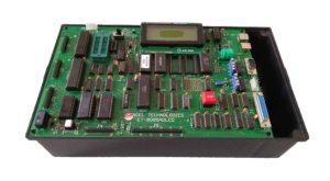
8085 MICROPROCESSOR KIT ( LCD VERSION)
Model No: ET –8085ADLCD
Specification:
- Memory CapacityMonitor : EPROM : 64KBBattery Backup : 16KBScratch Pad: 4KBADVANCED S/W: [Assembler:/ Disassemble]
*1 Pass line assembler
*2 pass Assembler
*2 pass Disassembler
*Basic interpreter
*Hex Dump.
Additional Serial and Parallel
Input/ Output :
SID/SOD based (8085)
INTERRUPTS:
* 8 Nos. Using 8259(8085)
*User Manual :
1) Student Workbook
2) Instructor Guide and Technical Reference
3) Lab Exercise Book for 8085.
Speed –
20 MHz crystal operated multi-output clock source to operate various resources on Mother Board like CPU,Baud rate, T/C etc.
*Parallel I/O
48 VO lines using two 8255 through 2 Nos. of 26 pin FRC header, printer I/F.
* Serial I/O
RS-232c serial interface using 8251 and RS232 driver IC
through 9 Pin male D connector.
* Timer counter
3 Nos. T/C using 8253 pins brought out on 6 pin reliamate / 26 pin FRC
Display : 16 X 2 LCD (Backlit)
- *Key Board:Single chip micro- controller 89C2051 to support 101 Keys PC AT / PS2 Keyboard and LCD *System Bus50 Pin FRC buffered Bus to connect per ware cards as well as to facilitate ROM Emulation of 8 bit/16 bit system memory using external ROM emulation card cum converter card.*Battery Backup
Rechargeable Ni cd battery (3.6/60maH) provide to Supply power to battery backup memory and RTC 58167 / 1202.
Onboard Features
* External Loud speaker (80hm/0.5w) interface for experiments on frequency synthesis.
* Reset and single step/interrupt push button.
* EP socket for experiments with cassette recorder interface.
* Programmable wait state generator I real Time clock IC 58167 /1202
* 1 Relay Output having 2NO & NC Contacts.
* 1 Opto isolated Input expandable to 4.
* 11 Nos. fault links to teach troubleshooting skills by introducing faults in the circuit.
*PALS-All glue logic like memory I/O decoders are implemented using 4(5) nos. of EEPROM PALS 16V8
- POWER Supply (SMPS)5V/2.5Amp SMPS With RCA plug +12 v/850 Ma,-12v2.5 mA with 4 pin reliamate SMPS.Cables and CD: 9 pin Female to 9 pin Female RS-23c cable, 26 pin FRC IO cable, USB to RS2232 Cable, sample program and software on CD.Fault Links:
*Shorts 2 pins of Address Bus.
*Shorts 2 pins of Data Bus.
*Shorts Adderess pin to Data Bus.
*Increasing Battery Discharge.
*Disables RD/ and WR/ into BBK RAM
*Permanent Wait State.
*Disables 7 Segment Scanning.
*Disables 7 Segment Data.
*Permanent Reset State.
* Stops 20MHz Clock.
* Disables Baud Rate Clock.
* Enclosed in ABS Plastic Box with Cover
